

TLIs (Ladder Instructions) |
This section documents in more detail the operation of the included ladder function blocks, the TLIs. For TOPDOC online, these instructions are automatically added to the instruction menu the moment you go online to a SoftPLC that has the GOVERNOR TLM installed and loaded.
Except for the PID SUPER LOAD and PID SUPER SAVE instructions, the remainder of these instructions are time based. Similar to our standard PID instruction, the time based instructions should be enabled only every so often. The interval between when they are enabled is called the update time. You can do this either by putting them all in a subroutine that is called only every update time or by conditionalizing them with a contact which is coming off of a free wheeling timer, whose preset is set to the update time.
LEAD LAG | ||
This instruction takes an input signal in float form and transforms it according to the industry standard lead lag algorithm. The block diagram for it in Laplace transform representation is as follows:
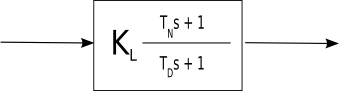
where KL is the steady state proportional gain, TN is the lead time constant in seconds and TD is the lag constant in seconds.
It takes the following instruction parameters.
| Parameter Name | Description |
|---|---|
| Input | is the input signal which is shown in the the above diagram coming in from the left side of the box. |
| Output | is the output signal which is shown in the the above diagram exiting to the right side of the box. |
| KL | is the steady state gain. It is often near 1.0. |
| TN | is lead time constant in seconds. As a memory aid, the "N" in TN stands for numerator. |
| TD | is the lag time constant in seconds. As a memory aid, the "D" in TD stands for denominator. |
| Delta T | is the update time in seconds. Set this to the interval period between calculations, which is every time the instruction is executed with a true rung condition. |
| Scratch | This is a block of float words that is used internally by the instruction to keep historical data between invocations. |
RAMP | ||
This instruction takes an input signal in float form and transforms it according to an integration or accumulation algorithm. The block diagram for it in Laplace transform representation is as follows:
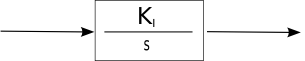
It can be used to ramp up or ramp down a setpoint, or to integrate a signal over time. It can also be used as part of a feedback loop or to simulate a process component.
It takes the following parameters:
| Parameter Name | Description |
|---|---|
| Input | is the input signal which is shown in the the above diagram coming in from the left side of the box. |
| Output | is the output signal which is shown in the the above diagram exiting to the right side of the box. |
| KI | is a gain or time constant. It establishes the rate of accumulation. If negative, the accumulated value will go down if the Input is positive. |
| Delta T | is the update time in seconds. Set this to the interval period between calculations, which is every time the instruction is executed with a true rung condition. |
| Scratch | This is a block of float words that is used internally by the instruction to keep historical data between invocations. The first word of this block is the Output on the last invocation. |
PID SUPER | ||
is a framework for a supervisory/adaptive/auto-tuning agent that sits on top of a standard PID controller and manages its operation. This instruction is a template for a C programmer to modify. It is probably only useful when the C source code is available for change. As structured, it takes an integer block, a float block, and PID element as parameters. A PID element is a standard data structure used by the standard PID instruction within SoftPLC. Together a PID element and a PID instruction make up a PID controller.
PID Super therefore has full access to all the data in the PID element including the update time, process output, PID gains, limits, etc. It may modify or examine any of these PID parameters depending on state data. You can have multiple sets of PID gains sitting in the float block and depending on which state you are entering, you can stuff the proper PID gains into the PID element upon transition in state. It can either rely on the standard PID instruction to execute after it does, or it can implement its own alternative PID algorithm. The demo code relies on the standard PID algorithm, and merely modifies the PID gains based on state.
In the sample code, the first integer in the integer block is expected to be set to a state variable elsewhere in the control logic to a value between 0 and 4, inclusive. Depending on which state is transitioned to, one of 5 separate gain sets are stuffed into the PID block.
Conceptually it looks like this:
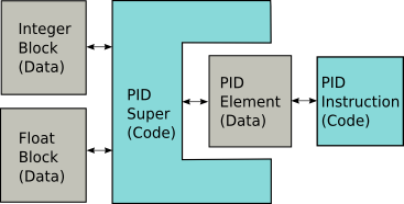
In the C source code the integer block and the float block are actually two separate C structures with each field having a convenient name. You are free to modify these C structure declarations to match your needs. The PID SUPER SAVE instruction is used to save these 2 structures to disk, and the PID SUPER LOAD instruction is used to load these 2 structures in from disk. If you modify the C source code for either struct mapped to the integer block or float block in PID SUPER, then you may also have to modify the two PID SUPER LOAD/SAVE instructions as well, or comment them out if you do not need them. Because the two blocks reside in the SoftPLC datatable, they can also be set via an HMI, TOPDOC NexGen, or a Servlet running under the Webserver.
This instruction takes only 3 parameters, but all 3 parameters are structures and therefore this instruction can operate on nearly any amount of data that you choose. Notice that there is no Delta T required, that is because you can reference the one in the PID element if you need one.
| Parameter Name | Description |
|---|---|
| PID Elem | is the PID Element that is managed. |
| Integers | is a block of up to 10,000 integers, with the actual size depending on the C source code. |
| Floats | is a block of up to 10,000 floats, with the actual size depending on the C source code. |
PID SUPER SAVE | ||
This instruction will write the block parameters for the PID SUPER instruction to a disk file. It can be used to save known working parameters. See the description in PID SUPER for more information. The save takes place when the instruction is energized.
| Parameter Name | Description |
|---|---|
| Integers | is a block of up to 10,000 integers, with the actual size depending on the C source code. |
| Floats | is a block of up to 10,000 floats, with the actual size depending on the C source code. |
| Filename | a STRING element which holds the name of the file to write to. |
| ErrorTxt | a STRING element which gets an error message if failure writing to disk, say because the requested directory does not exist. This string will be set to length zero if the write succeeds. |
PID SUPER LOAD | ||
This instruction will read the block parameters for the PID SUPER instruction from a disk file. It can be used to load known working parameters. See the description in PID SUPER for more information. The load takes place when the instruction is energized. The format of the file is all ASCII with name=value pairs on each line. So it may be edited with a text editor to parameterize a governor controller.
| Parameter Name | Description |
|---|---|
| Integers | is a block of up to 10,000 integers, with the actual size depending on the C source code. |
| Floats | is a block of up to 10,000 floats, with the actual size depending on the C source code. |
| Filename | a STRING element which holds the name of the file to read from. |
| ErrorTxt | a STRING element which gets an error message if failure either reading the disk file or parsing its contents. This string will be set to length zero if the write succeeds. |