

Usage
Installation
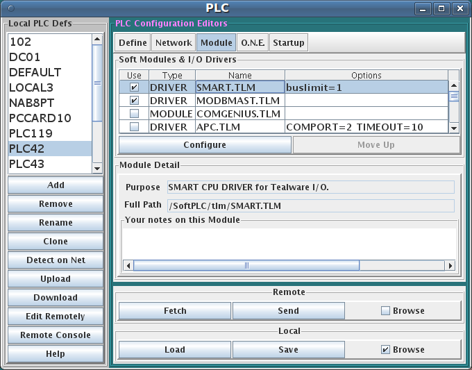
The TLM is named smart.tlm.so and is found as part of the standard SoftPLC 4.x installation in the /SoftPLC/tlm directory. To use it you merely have to enable it in NexGen's PLC | MODULES editor. Then you must edit the XML file SMART.XML which is the TLM's configuration file. There is an application specific editor for this SMART.XML file within NexGen. It is easy to edit the configuration file from the PLC | MODULES editor. Simply click on the Configure button after selecting and enabling Use in the same row as the SMART TLM.
Editor Usage
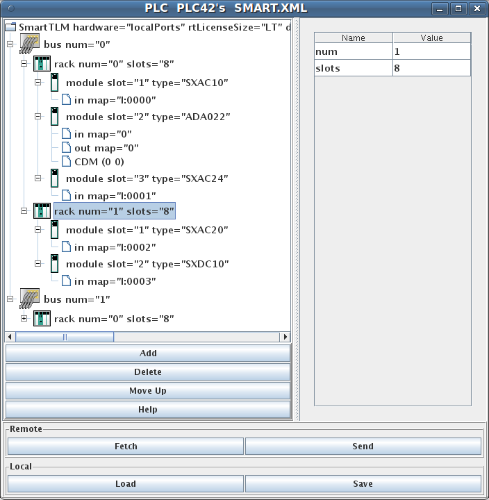
Add button will insert a new element within the selected element. First select the element you wish to insert into.
Delete button will deleted the selected element. It is only enabled when you are allowed to delete the selected element.
Move Up button will move the selected element up in the current containment list.
Fetch, Send, Load, and Save all have the same meaning as they do in the NexGen Module editor. You can see the helpfile for that editor by going to that editor and clicking on Help.
Use Send to transfer the configuration down to the SoftPLC. The next step is to cycle power on the SoftPLC for the changes to take place. As an alternative to cycling power, you may enter "Remote Program" mode using NexGen, then select "Remote Program" a second time. This psuedo transition from Remote Program to Remote Program is a signal to the TLM that it should reload its configuration file. This way you can reconfigure without cycling power, although it does require you enter "Remote Program" mode (twice!).
Popup Menus
There are a number of right click invoked popup menu choices that are available when there is a tree row selected.
One such choice that comes available when the top most element is selected, is called Delete Configuration on Smart . This choice will attempt to delete the SMART.XML file within the associated actual SoftPLC CPU. When that file is missing at the time of power up, then the TLM will automatically create one using a module detection scan loop through each rack and slot.
Another helpful menu choice Re-allocate All Datatable Addresses , which will change the in and out map attributes in an ascending sequence with no gaps.
There are other menu choices to sort slots or racks or buses, should you wish to renumber them manually, then have the menu option sort them into order again.
Ladder Instructions
This TLM implements a number of ladder instructions, one of communications health monitoring, another for talking to an HSC11 module in a special frequency measurement mode, and still others to transfer blocks of data to specialty I/O modules on demand.
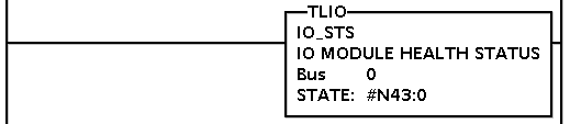
IO_STS
This instruction can be used to monitor the health of the communications to each and every I/O module within a local Tealware bus. You can program one of these instructions for each Tealware local bus that you have. It returns 4 words which are bitmapped with individual module status information for each slot on that bus. The first 24 bits of the word block are mapped to the 24 slots on the bus (3 racks x 8 slots max per rack), starting with the first 8 slots available to rack 0, then the next 8 slots for rack 1, followed by the last 8 slots for rack 2. Bits are allocated starting from bit 0 in the first word and continue into the least significant 8 bits of the 2nd word. The 3rd and 4th words are not used at this time but will be set to zeros.
| Parameter | Meaning |
|---|---|
| Bus: | An integer Tealware local bus number, 0-3. |
| State: | The address of an integer datatable block. The block's length is 4 words, and these 4 words receive the health status bits as decribed above, whenever the instruction is energized. |
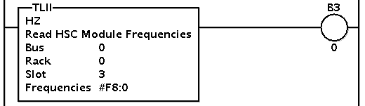
HZ
This instruction is only helpful when you have an HSC11 module and want to get frequency from it. The module maintains counts, not frequency, but with this instruction accurate timing information is applied to the counts to calculate frequency. To use this instruction, each of the module's 3 high speed counter channels must be put into the "continuous count up" mode. This instruction will convert each of those 3 increasing counts into a separate frequency, 3 separate frequencies per module. It is not possible to use less than all 3 channels on any given HSC11 in a non frequency mode. It is all or none.
To put each channel into the "continous count up" mode, it is a two step process. Firstly, the configuration file has to have a special XML element attached to it for any HSC11 module that you wish to operate in frequency mode. This will establish the continous count mode for all 3 channels on that module in software, but not the counting direction (up or down). The counting direction must be set by hardware separately for each channel by wiring a high signal to one of the channel's wiring terminals. Without this the frequencies will be negative.
| Parameter | Meaning |
|---|---|
| Bus: | The Tealware bus number, 0-3. |
| Rack: | The Tealware rack on said bus, 0-2. |
| Slot: | The Tealware slot number within said rack, 1-8. |
| Frequencies | The datatable address of a block of 3 floats which will receive the 3 channel frequency calculations in units of HZ (counts/second). |
Energizing the instruction causes both a new set of samples to be stored into each of the 3 sliding windows, and also the calculations to be performed and returned. The instruction might not need be energized on every scan.
For example, with a window size of 200, and the instruction energized every 100 msecs, this is a total span of time of 200 x .1 sec = 20 secs. So the calculation (frequency measurement) would give you an average frequency across the last 20 seconds, but do so every 100 msecs. If the window size was reduced down to 40 samples, then 40 x .1 sec = 4 seconds window width. If you wanted something even more responsive, say an average of the last 250 msecs, (a reasonable scenario in fluid flow metering application), and you had a program scan time of about 10 mescs, then you could set the window size at 250 and simply leave the instruction energized for every scan. Then 25 x .01 seconds = 0.250 seconds sliding window time span.