
1. Overview
1.1. Introduction
This document describes the installation, usage, and functionality of a TLM (TOPDOC Loadable Module) for SoftPLC version 3.x and later. This TLM implements the slave side of the Modbus Master/Slave protocol using a serial line. See and here and here for definitions of this protocol.
The TLM described by this document is called MODBSLAV. The Modbus Slave TLM is used to add Modbus slave capabilities to a SoftPLC runtime and to allow it to participate in master-slave communications between intelligent devices on a serial RS-232, RS-485, or RS-422 communications link.
SoftPLC offers other TLMs in support of Modbus TCP/UDP, as well as Modbus RTU/ASCII Master. This TLM only implements the serial line form of the protocol and only the slave side of it.
| Media Type | Master | Slave |
|---|---|---|
Serial Line |
*this TLM* |
|
TCP and UDP |
TLMs may be developed by any competent C/C++ programmer who has access to the SoftPLC C/C++ Programmer’s Toolkit, a product readily available from SoftPLC Corporation. There are a number of Systems Integrators who are SoftPLC Partners who possess the requisite expertise. End users may also have this capability.
1.2. Features
The Modbus Slave TLM operates as a SoftPLC driver and may be configured with TOPDOC NexGen. Modbus RTU and ASCII protocols are supported in SoftPLC version 4.6.160608 and later. For earlier versions only ModbusRTU protocol is supported.
Modbus protocol was originally developed to talk to Modicon PLCs, and therefore devices that implement the slave side of the protocol must recognize references to Modicon memory locations. This TLM maps SoftPLC datatable files into virtual Modicon PLC memory locations. This mapping is controlled in the configuration file of the TLM.
Up to 8 serial ports are supported. Possible baud rates are 2400, 4800, 9600, 19200, 38400 or 115200. Hardware handshaking is not supported, and this may make it difficult for slaves of this type to participate in a multi-drop bus without special RS-232 to RS-485 converters which would do the hardware handshaking. Hardware handshaking is not required for a single slave bus.
The TLM supports the following Modbus Functions:
| Function Number | Description |
|---|---|
0x01 |
Read Coils |
0x02 |
Read Input Discretes |
0x03 |
Read Multiple Registers |
0x04 |
Read Input Registers |
0x05 |
Write Single Output |
0x06 |
Write Single Register |
0x07 |
Read Exception Status |
0x08 |
Diagnostics |
0x0F |
Force Multiple Coils |
0x10 |
Write Multiple Registers |
0x16 |
Mask Write Registers |
1.3. Requirements
-
Version 3.x SoftPLC and TOPDOC NexGen version 1.3 or later.
-
For Modbus ASCII, version 4.6.160608 SoftPLC and TOPDOC NexGen version 1.6.160608 or later.
2. Terms of Use
Because of the variety of uses of the information described in this manual, the users of, and those responsible for applying this information must satisfy themselves as to the acceptability of each application and use of the information. In no event will SoftPLC Corporation be responsible or liable for its use, nor for any infringements of patents or other rights of third parties which may result from its use.
SOFTPLC CORPORATION MAKES NO REPRESENTATIONS OR WARRANTIES WITH RESPECT TO THE CONTENTS HEREOF AND SPECIFICALLY DISCLAIMS ANY IMPLIED WARRANTIES OF MERCHANTABILITY OR FITNESS FOR ANY PARTICULAR PURPOSE.
SoftPLC Corporation reserves the right to change product specifications at any time without notice. No part of this document may be reproduced by any means, nor translated, nor transmitted to any magnetic medium without the written consent of SoftPLC Corporation.
SoftPLC and TOPDOC are registered trademarks of SoftPLC Corporation.
© Copyright 2006-2016 SoftPLC Corporation ALL RIGHTS RESERVED
| First Printing |
January, 2006 |
| Last Printing |
June, 2016 |
SoftPLC Corporation
25603 Red Brangus Drive
Spicewood, Texas 78669
Telephone: 512-264-8390 or 800-SoftPLC (USA)
Fax: 512/264-8399
URL: http://softplc.com
Email: support@softplc.com
3. Configuration
Perform the steps in this section in sequence.
3.1. Module Editor
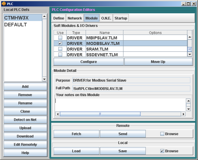
Use TOPDOC NexGen’s PLC » Module Editor to load and configure the MODBSLAV.TLM for use with SoftPLC, as shown in the figure below. Check Use to select to use the driver. This will enable the Configure button. Pressing Configure opens the configuration text editor.
If connected to your SoftPLC, then press Fetch to transfer the default MODBSLAV.LST file from the SoftPLC to the editor. If you are not connected, you can press Load to load the template configuration file from disk. This is the configuration file where you will assign the serial ports and datatable files to be used by the MODBSLAV driver. A maximum of 8 serial ports may be defined.
3.2. Modicon to Datatable Mapping
SoftPLC datatable files can hold up to 10,000 elements per file. Therefore any of the standard Modicon memory regions can have the following reference number ranges:
| Modicon Memory Type | Supported Reference Number Range |
|---|---|
Holding Registers |
400001 to 410000 |
Input Registers |
300001 to 310000 |
Input States |
100001 to 110000 |
Output Coils |
000001 to 010000 |
| Usually the Modicon memory regions are assigned to an 'N' (Integer) file within SoftPLC. The assignment must start at element number zero. Notice the N104:0 used in the example below. Any datatable file references made in the MODBSLAV configuration file MUST exist in the associated SoftPLC’s running APP file. This datatable memory must be created by using TOPDOC NexGen. This TLM does not automatically create this datatable memory for you. |
3.3. Sample Configuration File
The following is a sample MODBSLAV.LST file:
; This is the configuration file for the MODBUS Slave TLM.
; Anything after a semicolon is ignored during parsing.
; There are two sections: [DRIVER] and [PORTS]:

; [DRIVER] contains global options, such as DEBUG and IOCHECK
;
; Set DEBUG to > 0 if you want diagnostic output temporarily.
;  DEBUG=0 gives no diagnostic output.
;  DEBUG=1 gives a nice Query Response trace.
;  DEBUG=2 gives what 1 does and more.
;
; Set IOCHECK to YES if you want the turn around time to be reduced by
;  having SoftPLC service the modbus commands more frequently than once
;  per scan. This is effective only when you have more rungs than
;  STARTUP.LST's oneCheckInterval setting.
;
; Set XMIT_ONLY_IF_CTS to yes if you want the transmit process to be halted
; and conditional on the CTS line being asserted by the modem
;
; Set MODEM_WARMUP_TIME to the number of msecs that the transmit process should
; wait after asserting RTS and before transmitting.  If you don't want a delay
; other than what might be required by the XMIT_ONLY_IF_CTS setting, then set
; this to zero.  MODEM_WARMUP_TIME is non-zero, and XMIT_ONLY_IF_CTS is yes,
; then both conditions must be true before transmitting takes place.
;
; Set HOLD_RTS_AFTER_LAST_BIT_USECS to the number of microseconds (usecs not msecs)
; that the driver should hold up RTS after the last byte of a reply has been
; transmitted.  This is only in affect when XMIT_ONLY_IF_CTS is set to YES.
; In one application at 1200 baud, a value of 8000 was the only one that worked.
;
; Set INTER_CHAR_GAP_COUNT to the inter character gap timeout.  If there
; is an idle gap in the command packet input stream longer than this count, then
; the internal state machine goes back to the state which looks for a match on
; the station address.  That is it goes looking for the beginning of a new packet
; and aborts any partial packet up to that point.  The units of this setting is
; "character time" which is how long it takes for one byte with stop, start and parity
; bits to travel at that given baudrate.  The modbus RTU spec calls for 4.  This
; setting only has an effect in RTU mode.  If not set, there is an internal default
; larger than zero.

[DRIVER]

; Bit mapped DEBUG word turns on selective categories of printing based on the
; bit value for each category.  Use hex to set.
; BitNum        Category
;==========     =================================================
; 0             General Debugging
; 1             Tell when RTS is toggled.
; 2             Print all REPLYs that I send in hex bytes
; 3             Print all QUERYs that I receive in hex bytes
; 4             Print timing of replies that I send
; 5             Print start of a query that is for me.
; 6             Print RX_STATE transitions
; 7             Print TX_STATE transitions
; 8             Print QUERYs that have wrong station addresses, for other nodes
; 9             Print partial quries that were victim of inter character timeouts
; 10            Print Queries that had bad CRCs.

DEBUG=0x0000


IOCHECK=YES
XMIT_ONLY_IF_CTS=NO
MODEM_WARMUP_TIME=0                 ; Mille Modem uses 40 here  This is in milliseconds
TWO_WIRE_RS485=YES                  ; set to YES if 2 wire RS485, this turns on ADC on SMART

HOLD_RTS_AFTER_LAST_BIT_USECS=8000  ; usecs time to keep RTS up after last byte we send.
;INTER_CHAR_GAP_COUNT=7             ; maximum inter character gap time in "character times"


; [PORTS] should include one line for each serial port you want active.
; All the StartAddress's must be based at element zero of a file of one
; of the following types: INTEGER, BIT, INPUT, or OUTPUT.

[PORTS]
;PORT: 0-31 indicating the serial port number. (On x86: 0=COM1, 1=COM2, etc.)
;|  Baudrate: 2400, 4800, 9600, 19200, 38400 or 115200
;|  |       Databits: 8
;|  |       |  Parity: N or E or O
;|  |       |  |  Stopbits: 1 or 2
;|  |       |  |  |  Modbus slave address: 1 - 247 or -1 to indicate "wildcard"
;|  |       |  |  |  |   Holding Registers StartAddress:
;|  |       |  |  |  |   |        Output Coils StartAddress
;|  |       |  |  |  |   |        |        Input Registers StartAddress
;|  |       |  |  |  |   |        |        |         Input States StartAddress
;|  |       |  |  |  |   |        |        |         |		Framing (RTU or ASCII)
;|  |       |  |  |  |   |        |        |         |		|
 0, 38400,  8, N, 1, 1,  N10:0,   N11:0,   N12:0,    N13:0,	RTU

;1, 19200,  8, N, 1, 4,  N100:0,  B3:0,    N7:0,     I:0,	ASCII    spare as needed

; Make sure you use TOPDOC to create the Datatable Files that you are
; referencing for each port.

;EOF
3.4. Final Steps
-
After you have finished configuring the driver, press Save and then Send. This will save the MODBSLAV.LST file to your TOPDOC NexGen PC and then transfer the file to the SoftPLC’s Flash disk.
-
Now reboot the SoftPLC controller. SoftPLC is now ready to process Modbus serial data requests from the Master.
-
The last step is to program the Modbus Master to send the read and write request(s) to the SoftPLC Modbus Slave.
4. Debugging Tips
This section gives tips on debugging problems on the Modbus network.
4.1. Enabling Debug Prints
In the configuration file there is the DEBUG setting. It may be set to 0, 1 or 2 to indicate that you want no, some, or most debugging respectively. Remember a DEBUG value of "0" means no debugging.
On version 4.x SoftPLC, all process output from the SoftPLC runtime engine is normally directed to the syslog, because SoftPLC runs as a daemon normally. The syslog can be configured in a number of different ways, but the default uses a small RAM resident FIFO and eventually will run out of space and wrap back around on itself. Rather than reconfiguring the syslog, there is an easier way, described below.
Following is a procedure to get the debugging output into a text file:
-
Log into SoftPLC using either a) PUTTY from Windows or b) using ssh from Linux or c) at the command prompt of the SoftPLC system.
-
Run this command:
# /etc/init.d/softplc.sh stop -
Change into the /SoftPLC/run directory:
# cd /SoftPLC/run -
You can run SoftPLC from the command prompt now and redirect its output to an arbitrary file (named out.txt here). We put that file into the RAM disk which is anchored in the /tmp directory. # ./runsplc > /tmp/out.txt
-
Let this run for 5-60 seconds, then press control-C. Now you have the output captured in file /tmp/out.txt, each request-response transaction will have been captured in that file.
-
You can look at the file using the program named "less".
# less /tmp/out.txt
Review this output using the Modbus Specification and the manual for your Modbus master software/device. Press ESC when done. -
When done, remember to set debug back to "0", then you can start SoftPLC as a daemon either by a) power cycling the box or b) doing the following:
# /etc/init.d/softplc.sh start