
1. Overview
1.1. Introduction
This document describes the installation, usage, and functionality of a TOPDOC Loadable Module (TLM) for SoftPLC version 4.x and later. The TLM implements the master (or client) side of the Modbus TCP protocol. As an extension of the standard, it also implements the same protocol on UDP/IP.
This TLM may be used to monitor and control ethernet based I/O and MMI graphical user interface stations, or it may be used to communicate with other controllers on an ethernet. Modbus protocol was designed for communicating with Modicon PLC’s and was not designed for communicating with I/O. However, this TLM is an I/O driver first and foremost, and a peer to peer messaging service secondarily. Therefore it takes special steps to overcome most shortcomings in the Modbus protocol with respect to I/O control, resulting in a good I/O solution to most control applications.
This driver can be used without any application program logic required for configuring I/O modules or firing messages. Messages are ear-marked for either "configuration" or "RUN mode continuous" purposes. Configuration messages take place automatically just as SoftPLC enters RUN mode. RUN mode continuous messages are issued cyclically any time SoftPLC is in RUN mode. Lastly, the RUN mode continuous messages automatically use alternate "write" data on the last scan before SoftPLC enters PROGRAM mode, and thus the process outputs will be turned off as you would expect.
1.2. Definitions
-
Modbus TCP protocol is similar to simple Modbus serial protocol. Modbus TCP runs on top of a TCP/IP connection and has a 6 byte header at the beginning of each simple modbus frame, where frame means either a request or response packet.
-
Modbus UDP protocol is nearly identical to Modbus TCP except that it runs connectionless on UDP/IP. Unlike TCP which is a gauranteed delivery service, when using UDP the application layer is responsible for any retries required due to possible loss of frames.
-
A Modbus transaction is master - slave in nature, and consists of the master node sending a request and the slave node replying to the request with a response. The master node always sends the request and the slave node always sends the response. The slave node only speaks when spoken to with a request. Each request is owed exactly one response.
-
The term client is an alternative to master. The term server is an alternative to slave.
-
Some requests may be earmarked as configuration requests, so that they are only sent when it is appropriate to configure an I/O module.
-
In this TLM, all output (Modbus "write") requests have two alternative forms of output data associated with them, live data and idle data. Which of the two forms of data is used depends on the SoftPLC runtime engine’s Operating Mode.
-
Modbus IP means either Modbus TCP or Modbus UDP but not simple Modbus serial protocol.
1.3. Concepts
The SoftPLC runtime engine software supports TLMs, which are shared library extensions to SoftPLC. A TLM may be loaded either as a DRIVER or as a MODULE. The difference between a DRIVER and a MODULE is that a DRIVER is called once per SoftPLC scan, and optionally an additional number of times per scan. A MODULE is only called when the control program decides to call it and not as an inherent part of the scan. TLMs are made known to SoftPLC in the MODULES.LST file which may be edited by TOPDOC NexGen by traversing to: PLC | Modules.
1.4. Features
In order to use the modbus IP master TLM you need a working ethernet connection. This TLM takes a configuration file named MBIPMAST.XML and acts as a "scanner" or as "master" or a "client", three terms which mean the same thing in the context of Modbus IP. On the other end of any Modbus conversation is a "slave" or a "server". Because the master implemented by this TLM supports both TCP and UDP carriers for the Modbus protocol, this allows you to talk to slaves which implement MODBUS/UDP in addition to slaves which implement only MODBUS/TCP. Up to 128 servers are supported by this master. Each slave may be addressed using TCP or UDP, or both.
When TCP is used by the master, there is a TCP connection established. When UDP is used by the master, the request response sequence takes place in a "connection-less" fashion. Because UDP is not a guaranteed delivery service, any Modbus master using UDP instead of TCP to carry the modbus requests and responses should implement timeout and retry logic. This master TLM allows you to configure the response timeout and attempts for each UDP server uniquely.
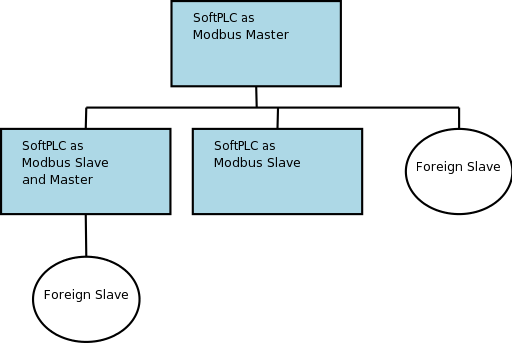
SoftPLC also provides a Modbus IP Slave TLM, which is documented here. A single SoftPLC machine can be both a master and a slave. This capability gives the systems designer the power and flexibility to develop very powerful, fast and flexible distributed control systems. Obviously a SoftPLC Modbus master can talk to a SoftPLC Modbus slave as well as third party slaves.
The following is a list of the Modbus Commands, and whether they are supported or not:
| Modbus Function | Name | Supported? |
|---|---|---|
1 |
Read Coils |
Yes |
2 |
Read Input Discretes |
Yes |
3 |
Read Multiple Registers |
Yes |
4 |
Read Input Registers |
Yes |
5 |
Write Coil |
Yes |
6 |
Write Single Register |
Yes |
7 |
Read Exception Status |
No |
15 |
Force Multiple Coils |
Yes |
16 |
Write Multiple Registers |
Yes |
20 |
Read General References |
No |
21 |
Write General Registers |
No |
22 |
Mask Write Register |
Yes |
23 |
Read Write Registers |
Yes |
24 |
Read FIFO Queue |
No |
1.5. Requirements
-
A working ethernet or PPP link.
-
Version 4.x SoftPLC or later.
2. Terms of Use
Because of the variety of uses of the information described in this manual, the users of, and those responsible for applying this information must satisfy themselves as to the acceptability of each application and use of the information. In no event will SoftPLC Corporation be responsible or liable for its use, nor for any infringements of patents or other rights of third parties which may result from its use.
SOFTPLC CORPORATION MAKES NO REPRESENTATIONS OR WARRANTIES WITH RESPECT TO THE CONTENTS HEREOF AND SPECIFICALLY DISCLAIMS ANY IMPLIED WARRANTIES OF MERCHANTABILITY OR FITNESS FOR ANY PARTICULAR PURPOSE.
SoftPLC Corporation reserves the right to change product specifications at any time without notice. No part of this document may be reproduced by any means, nor translated, nor transmitted to any magnetic medium without the written consent of SoftPLC Corporation.
SoftPLC, and TOPDOC are registered trademarks of SoftPLC Corporation.
© Copyright 2005 SoftPLC Corporation ALL RIGHTS RESERVED
| First Printing |
July, 2005 |
| Latest Printing |
July, 2005 |
SoftPLC Corporation 25603 Red Brangus
Drive Spicewood, Texas 78669
USA Telephone: 1-800-SoftPLC
Fax: 512/264-8399
URL: http://softplc.com
Email: support@softplc.com
3. I/O Scanning
This TLM is primarily intended for controlling ethernet based I/O. As an I/O driver, it assumes the normal burdens of a SoftPLC I/O driver pertaining to the management of operating modes and states, described below.
3.1. Operating Modes and States
The SoftPLC runtime engine is always in one of the following states, called Operating Modes.
| Mode | Description |
|---|---|
Program or Remote Program |
Logic is not being solved and the outputs are in an idle state. Normally idle state means "turned off or zeroed", but with this driver, each output is independently configurable to be other than off or zero in its idle state. For example, a valve can be configured to be at 50% open in its idle state. If you take no special steps, the idle state of an output is zero or off. |
Run or Remote Run |
Logic is being solved and the outputs are active and under the control of the logic program. They are not idle. The logic program makes its decisions based on the current state of each input, all of which are actively scanned. |
Test or Remote Test |
Logic is being solved but the outputs are idle. The logic program makes its decisions based on the current state of each input, all of which are actively scanned. |
Faulted |
Logic is not being solved and the outputs are idle. This mode is entered automatically if you have an error in your program or in one of your driver configurations. |
Each configured Modbus IP slave is always in one of the following states. Each slave’s state is independent of the state of any other slave, so not all slaves are always in the same state.
| State of Slave | Description |
|---|---|
Present and Responding |
The TLM has a good connection to the slave and knows that it is responding within a timeout limit to its requests. A subset of this state is the situation where the slave responds with an exception to a request. |
Not Present or Not Responding |
The TLM is not able to get any response to its requests from this slave. This is the case when the cable is disconnected, the slave is not powered up, or the slave has failed. |
The two states shown are tracked by the TLM for each slave. The Present and Responding state is used for all 4 Operating Modes. As long as an I/O module is responding, the TLM can tell it what to do and thereby honor its obligations with respect to Operating Modes. The slaves have no actual knowledge of the SoftPLC Operating Modes per se. An output module is told to go "idle" merely by sending the corresponding process data to the module. The module does not know the data is "idle" data, only the TLM does.
3.2. Driver State Transitions
The SoftPLC runtime engine notifies all TLMs of the need to change from one Operating Mode to another. A TLM that is acting as an I/O driver must honor the behavior outlined in the Operating Modes table above. To accomplish this, there are significant responsibilities that must be met at the edge of these mode transitions.
Additionally most Modbus IP I/O modules these days are intelligent and can be software configured to operate with alternative behaviors. The soft configuration normally takes place by sending regular Modbus requests, but with special memory addresses used in the requests that are reserved for configuration.
This soft configuration may be required when entering Run mode, or it may be required just after an I/O module is replaced, possibly due to an I/O module failure. The I/O module replacement might take place while the SoftPLC runtime engine is in Run mode the entire time. The I/O driver must therefore detect that the I/O module is newly present, and send the configuration commands on the edge of this transition from not present to present.
| Object | Transistion | Description |
|---|---|---|
Runtime Engine |
From Run Mode to Program, Faulted, or Test |
The TLM issues the output requests to the output modules with the idle data on a one shot basis. |
Runtime Engine |
From Test, Program, or Faulted to Run Mode |
The TLM issues the configuration requests to all modules on a one shot basis. |
Any Slave |
From Not Present to Present |
The TLM issues the configuration requests to this module on a one shot basis. |
3.3. Scan Synchronization
The TLM has its own thread (scanner thread) with its own scanning operation. This scanner thread is separate from the main control program thread (main thread) which is part of the SoftPLC runtime engine. The scanner thread runs in parallel with the main thread. Naturally the two threads can have different work loads and will rarely complete their respective scan cycles in the same amount of time. The following rules are put into effect:
-
If the scanner thread completes a given scan cycle before the main thread, then the scanner thread waits for the main thread to complete before starting its cycle again. (No cpu time is wasted during the wait.)
-
If the main thread completes before the scanner thread, it does not wait for the scanner thread, and the two threads both run as fast as they can, with the main thread running at a faster cycle rate.
In other words, the scanner thread is not allowed to wastefully use CPU cycles obtaining fresh I/O status only to have it not used. On the other hand, if this Modbus master scanner thread is running slower than the main thread, then only the I/O on the ethernet is updated slower. Any other I/O drivers (TLMs) and the main thread are not slowed down due to a slow ethernet module.
| The modbus scanner thread’s scan cycle time is dictated by the worst case response time from any of the ethernet I/O modules (modbus slaves) on the I/O ethernet. Therefore if the overall I/O scan time of the ethernet I/O modules is important, make sure all of your ethernet I/O modules have an acceptable response time, because the slowest slave will dictate the I/O scan time for all others. Remember though, the modbus scanner is allowed to run slower than the main thread’s scan and therefore the other (non-Modbus IP) I/O drivers will not be slowed down by a slow ethernet module. (SoftPLC can have multiple I/O drivers active, only one of which may be modbus master.) |
3.4. Network Concerns
The modbus scanner thread issues many of the requests all at once and then services the responses as they come back asynchronously. This gives the best modbus I/O scan times because all the slaves are handling their respective requests in parallel. However, it can lead to choppy network traffic with higher instantaneous bursts of traffic at the start of each I/O scan. For this reason and for reasons of reliability and overall consistency of performance, it is recommended, but not mandatory, that a dedicated ethernet be used for the I/O modules and this master, particularly if you have more than a handful of slave nodes.
4. Configuration
4.1. Modbus Fields
Modbus commands were originally designed for a Modicon PLC. Therefore they assume 4 different types of memory regions. Words within these memory addresses are addressed using Reference Numbers, according to the following table. Basically, the first character of a reference number gives its region:
| Memory Region | Reference Number Format |
|---|---|
Input Discrete (boolean inputs) |
1… e.g. 120438 |
Input Registers (16 bit words) |
3… |
Output Coils (boolean outputs) |
0… |
Output Registers (16 bit words) |
4… |
Modbus TCP protocol includes the original slave id field which was part of the modbus on serial line protocol. In the case of communications on ethernet, either via TCP or UDP, this field is no longer used to qualify the actual network node that will respond to a request. The reason for this is because the IP Address in the ethernet frame serves this purpose. Therefore the "slave id" field becomes available for another use. This TLM can be configured to use a slave id field of your choosing for any request.
4.2. Configuration Fields
This TLM is configured using a special configuration editor which is built into TOPDOC NexGen. The configuration file is organized hierarchically with the following building blocks (elements). Sub Elements are listed with one of the following characters trailing (suffix), indicating that zero or more elements must or may be present according to the following interpretation:
-
Question Mark (?) ⇒ Optional (zero or one)
-
Asterisk (*) ⇒ Zero or more
-
Plus Sign (+) ⇒ One or more
-
None (no suffix) ⇒ exactly once
| Element Name | Description | Sub Element(s) |
|---|---|---|
ModbusTLM |
Top most element, holds all other elements |
TealwareDrop*, TCPServer*, UDPServer* |
TealwareDrop |
A TCPServer that uses hardware configuration to generate Modbus requests. |
Rack+, Slave+ |
TCPServer |
A network node that is a Modbus/TCP slave/server. |
Slave+ |
UDPServer |
A network node that is a Modbus/UDP slave/server. |
Slave+ |
Rack |
A Tealware Rack |
module+ |
module |
A Tealware Module |
address, CDM? |
address |
Describes the memory areas that a module references. |
|
CDM |
Configuration Data Memory |
|
Slave |
Provides the slave ID within a Server. |
ReadInputDiscretes+, ReadInputRegisters+, ReadMultipleRegisters+, ReadCoils+, WriteSingleRegister+, WriteMultipleRegisters+, MaskWriteRegister+, ForceMultipleCoils+, WriteCoil+, ReadWriteRegisters+ |
ReadInputDiscretes |
A Modbus request of the same name |
refNum, toBlock |
ReadInputRegisters |
A Modbus request of the same name |
refNum, toBlock+ |
ReadMultipleRegisters |
A Modbus request of the same name |
refNum, toBlock+ |
ReadCoils |
A Modbus request of the same name |
refNum, toBlock |
WriteSingleRegister |
A Modbus request of the same name |
refNum, fromBlock |
WriteMultipleRegisters |
A Modbus request of the same name |
refNum, fromBlock+ |
MaskWriteRegister |
A Modbus request of the same name. The "or mask" comes from the value of the fromBlock |
refNum, andMask, fromBlock |
ForceMultipleCoils |
A Modbus request of the same name |
refNum, fromBlock |
WriteCoil |
A Modbus request of the same name |
refNum, fromBlock |
ReadWriteRegisters |
A Modbus request of the same name |
refNum, toBlock+, refNum, fromBlock+ |
refNum |
A modicon reference number |
|
toBlock |
Where the response data is to be written into SoftPLC |
|
fromBlock |
Where the request data is read from SoftPLC |
(idle or const)? |
andMask |
An integer constant, see the Modbus specification for the MaskWriteRegister request. The orMask is given by the fromBlock for this request. |
|
idle |
A list of integer constants. These data will be sent on a one-shot basis to the slave when the Operating Mode calls for outputs to be idle. Otherwise, when outputs are not idle, the live data specified in the fromBlock are used. |
| When using NexGen to edit the configuration file, its application specific editor takes care of enforcing the rules of the configuration file. |
| Notice that a few of the word oriented requests can take multiple fromBlocks and/or multiple toBlocks. In the case of read word requests, the multiple toBlocks are used to split up the response into several SoftPLC memory locations. So you can route your discrete input data into the INPUT datatable section and your analog data into an INTEGER datatable section, should they need to be in the same response. Each toBlock "consumes" some of the response data consecutively, according to its count field. So the sum of all the count fields should not exceed the allowed limit for the request’s response. Likewise, for word write requests, multiple fromBlocks are supported. This allows you to assemble a request using data from multiple sources within SoftPLC. Your discrete output data can come from the OUTPUT datatable section and your analog data can come from an INTEGER datatable section, and be part of the same request. Again, the sum of the count fields for the fromBlocks cannot exceed the limit for the request. Input data that you put into the INPUT datatable section with a toBlock will automatically feature the Input Forcing cabability within the SoftPLC runtime. Output data you get from the OUTPUT datatable section using a fromBlock will automatically feature the Output Forcing capability within the SoftPLC runtime. Only those two sections support forcing, a feature which is mostly helpful for discrete I/O, and not usually analog data. |
Here is a sample screen from the configuration editor showing a few of the elements from the above table. Notice how they are arranged hierarchically and that each element can "contain" other elements. The rules of containment are given in the table Elements and their Allowed Sub-Elements:
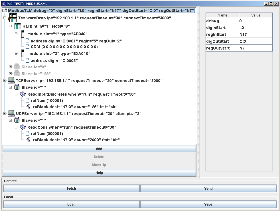
The element name is at the far left of each row. To the right of the element name is a list of attributes. The following table lists the allowed attributes for each element type:
| Element | Attribute | Value | Required |
|---|---|---|---|
ModbusTLM |
debug |
0, 1, or 2, meaning "enable none, some, or all debugging print statements |
no, defaults to 0 |
digInStart |
The start address for digital inputs in word form |
yes, defaults to I:0 |
|
regInStart |
The file to be used for register inputs |
yes, defaults to N17 |
|
digOutStart |
The start address for digital outputs in word form |
yes, defaults to O:0 |
|
regOutStart |
The file to be used for register outputs |
yes, defaults to N7 |
|
TealwareDrop |
ip |
The ip address or machine name of the server/slave, e.g. "192.168.12.3" or "packer12" |
yes |
connectTimeout |
Milliseconds to wait for a connection attempt to complete |
yes |
|
requestTimeout |
Milliseconds to wait for a response to a request, for any request contained by this element. |
no, defaults to 30 |
|
TCPSever |
ip |
The ip address or machine name of the server/slave, e.g. "192.168.12.3" or "packer12" |
yes |
connectTimeout |
Milliseconds to wait for a connection attempt to complete |
yes |
|
requestTimeout |
Default milliseconds to wait for a response to a request, for any request contained by this element. May be overridden by a specific request’s requestTimeout |
no, defaults to 30 |
|
UDPSever |
ip |
The ip address or machine name of the server/slave, e.g. "192.168.12.3" or "packer12" |
yes |
requestTimeout |
Default milliseconds to wait for a response to a request, for any request contained by this element. May be overridden by a specific request’s requestTimeout. |
no defaults to 30 |
|
attempts |
Count how many times to send the request before giving up waiting for a reply. |
no, defaults to 3 |
|
Rack |
num |
This rack’s number (from 1-4) |
yes, automatically assigned |
slots |
The number of slots this rack has (4, 6, or 8) |
yes |
|
module |
slot |
Which slot in the rack this module is located at |
yes, automatically assigned |
type |
The name of this module |
yes |
|
address |
digIn |
The digital input word address this module will reference |
no, will be present if the module calls for it |
regIn |
The register input word offset this module will reference |
no, will be present if the module calls for it |
|
digOut |
The digital output word address this module will reference |
no, will be present if the module calls for it |
|
regOut |
The register output word offset this module will reference |
no, will be present if the module calls for it |
|
CDM |
const values for CDM |
no, will be present if the module uses CDM |
|
Slave |
id |
"0" to "255", provides the slave ID within a Sever. |
yes |
<any request> |
when |
"run" or "start": run ⇒ when in a run mode, start ⇒ one shotted when entering a run mode |
no, defaults to "run" |
requestTimeout |
Milliseconds to wait for a response to a request |
no, defaults to the setting within the Server |
|
refNum |
|||
toBlock |
dest |
a SoftPLC word or bit address, e.g. "I12:0". If the enclosing request reads registers (not coils or discretes), then a word address is required. If instead the enclosing request reads coils or discretes, then a bit address may be supplied but its bit component must be zero. |
yes |
count |
the number of 16 bit words or the number of bits, depending on the enclosing request and the fmt attribute of this toBlock. |
yes |
|
fmt |
format of the response data, and determines the interpretation of the count attribute. "i2" or "bit": i2 ⇒ 16 bit (2 byte) signed integers, bit ⇒ bits. |
yes |
|
fromBlock |
source |
a SoftPLC word or bit address, e.g. "O12:0". If the enclosing request writes registers (not coils or discretes), then a word address is required. If instead the enclosing request writes coils or discretes, then a bit component may be non-zero. |
yes |
count |
the number of 16 bit words or the number of bits, depending on the enclosing request and the fmt attribute of this fromBlock. |
yes |
|
fmt |
format of the response data, and determines the interpretation of the count attribute. "i2" or "bit": i2 ⇒ 16 bit (2 byte) signed integers, bit ⇒ bits. |
yes |
|
andMask |
| In most cases where an "integer constant" is allowed, for example in the andMask, idle, or const elements, you may enter that value in either hex or decimal. Hex numbers start with a leading "0x". Example: "16" or "0x0010" would be OK. |
5. Usage
5.1. Installation
The TLM is named mbipmast.tlm.so and is found as part of the standard SoftPLC 4.x installation in the /SoftPLC/tlm directory. To use it you merely have to enable it in NexGen’s PLC | MODULES editor. Then you must edit the xml file MBIPMAST.XML which is the TLM’s configuration file. There is an application specific editor for this MBIPMAST.XML file within NexGen. It is easy to edit the configuration file from the PLC | MODULES editor. Simply click on the Configure button after selecting and enabling Use in the same row as the MBIPMAST TLM.
5.2. Editor Usage
Add button will insert a new element within the selected element. First select the element you wish to insert into.
Delete button will deleted the selected element. It is only enabled when you are allowed to delete the selected element.
Move Up button will move the selected element up in the current containment list.
Fetch, Send, Load, and Save all have the same meaning as they do in the NexGen Module editor. You can see the helpfile for that editor by going to that editor and clicking on Help.
Use Send to transfer the configuration down to the SoftPLC. The next step is to cycle power on the SoftPLC for the changes to take place. As an alternative to cycling power, you may enter "Remote Program" mode using NexGen, then select "Remote Program" a second time. This psuedo transition from Remote Program to Remote Program is a signal to the TLM that it should reload its configuration file. This way you can reconfigure without cycling power, although it does require you enter "Remote Program" mode (twice!).
With a (or multiple) TealwareDrop present, using Save or Send, the configuration editor will run a verification check on the address references used in all modules. If any overlaps are found, the error will be shown; otherwise the editor will then automatically generate Slave elements with Modbus requests as appropriate for all the modules. These elements cannot be edited, and any changes that may be needed should be made by editing the actual module element or its address component. For more information on TealwareDrop elements and their components, see the Configuration page.
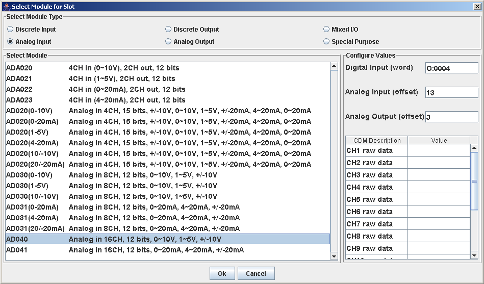
The Module Selection dialog is used to assign Tealware modules to specific slots in a Rack.
The Select Module Type box allows you to choose which types of modules you want to view when choosing what to add.
The Select Module box shows a list of all modules of the selected type with descriptions.
Configure Values displays the input and/or output areas for the module, as well as a table to configure the CDM data for the module (if present). Default values are supplied by the configuration tool and are automatically incremented as modules are added, but these values can be changed manually at any point. Values for digital addresses are word references, while analog addresses are input as an offset from word 0 in the file given by the ModbusTLM element.
Ok will add the selected module to the Rack, while Cancel will take no action and close the dialog.
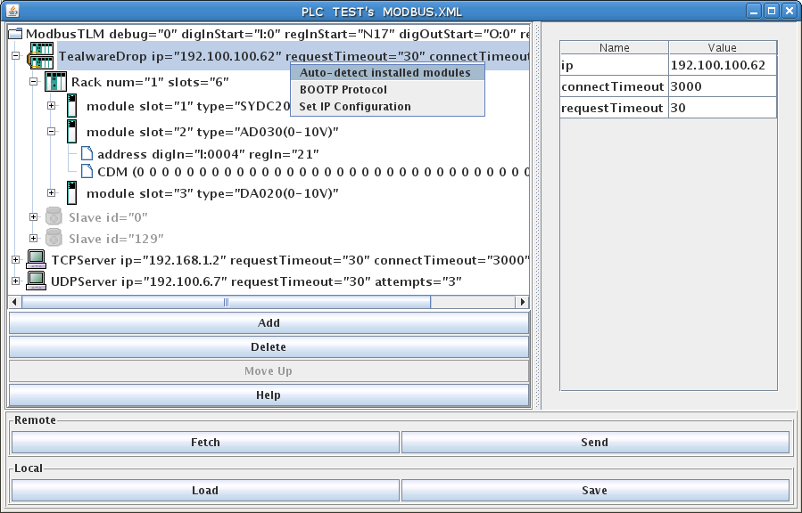
The configuration editor also provides a network discovery utility that can detect what Racks and modules are present in a Tealware Drop. Selecting the desired TealwareDrop element and right-clicking on it will show the menu options for the network utilities: Configure this TealwareDrop and BOOTP Protocol. The first option looks on the network at the IP Address specified for the selected Drop and (if successful) discovers what is present. The components for the TealwareDrop are then added and configured using the auto-increment functionality to assign addresses for the modules. Any CDM data must be manually entered.
The second menu option will open a new dialog window that will use the BOOTP Protocol to configure the selected TealwareDrop with an IP Address.
Right-clicking with the ModbusTLM root element selected will bring up an option to Discover/Configure all Tealware Drops. This performs the same function as for an individual element, but will find and add any TealwareDrop elements as well as their componenets.
5.3. Ladder Instructions
This TLM implements a few ladder instructions which are useful for diagnostics and fault situations.
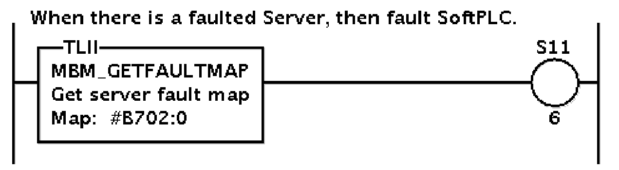
5.3.1. MBM_GETFAULTMAP
This instruction can be used to fetch a bitmap of up to 128 Servers, which is the maximum number of Servers supported by this TLM. The bitmap is copied into the Map: parameter which must be a block of 8 words. If a Server is in the not Present and not Responding state, then its corresponding bit will be set, else not.
This is a permissive instruction and it will evaulate to false when all the bits in the bitmap are zero, meaning no faults, all Servers operating fine. If any Server is in the Not Responding state, then its corresponding bit will be set in the bitmap and the instruction will evaluate to true. If it is your desire to stop the control when a Server fails, then something like the following rung of logic will fault SoftPLC when any Server fails, since turning on bit S11/6 will initiate a fault shutdown:
| Parameter | Meaning |
|---|---|
Map: |
A block address of 8 words which will receive a bitmap of all the configured Servers. We suggest using a block address in a 'B' datatable file so that the bit numbers ascend from zero accross word boundaries, thus corresponding to Servers in the configuration file. The first listed Server in the configuration file is 0, the second is 1, etc. |
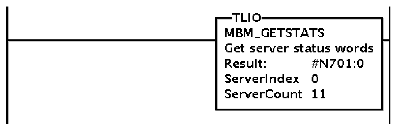
5.3.2. MBM_GETSTATUS
This instruction can be used to fetch 5 status words for each Server in a range of Servers. The range of Servers can be any number but must be contiguous as defined within the configuration file. The 5 status words for each Server fetched will be contiguous within the Result block parameter, and their meaning is as follows: (Meanings are for a single specific Server)
| Word Index | Status Counter Meaning |
|---|---|
0 |
average response time in msecs |
1 |
TCP: no. times the slave timed out or responded with an exception / UDP: no. retried requests |
2 |
no. of times TLM saw an exception |
3 |
set to modbus commmand code of any that is answered with an exception |
4 |
set to the modbus exception code, or 0 if no exception but rather a timeout occurred |
This instruction can be used to monitor the health, performance, and connection integrity of any or all Servers.
| Parameter | Meaning |
|---|---|
Result: |
A block address of 640 (=5*128) words which will receive a number of groups of 5 words, depending on how many Servers are requested. The pattern of 5 words is repeated one after another according to the Status Counter table above. |
ServerIndex |
The starting index of the first Server of interest within the list of Servers given in the configuration file. |
ServerCount |
The number of contiguous Servers of interest within the list of Servers given in the configuration file. In the example rung above, there will be 11 Servers fetched starting at Server 0. |
5.3.3. MBM_CLEARSTATUS
This instruction clears the 5 status words (to zero) for each Server in a range of Servers. The range of Servers can be any number but must be contiguous as defined within the configuration file. The 5 status words for each Server cleared will be contiguous within the Result block parameter, and their meaning is as given in MBM_GETSTATUS
This instruction can be used to get a fresh start, say after power cycling your slaves or modifying the cabling, when you might want to erase the history of previous problems.

| Parameter | Meaning |
|---|---|
ServerIndex |
The starting index of the first Server of interest within the list of Servers given in the configuration file. |
ServerCount |
The number of contiguous Servers of interest within the list of Servers given in the configuration file. In the example rung above, there will be 11 Servers cleared starting at Server 0. |
6. Debugging
This section gives tips on debugging problems on the Modbus network.
6.1. Isolating the Problem Slave Node
During startup or when troubleshooting a problem node it is usually best to isolate the problem node. This means look at it in isolation, by making it the only active slave on the network. You can keep the other slaves connected, but use a temporary configuration file to announce to the TLM only the node that you are troubleshooting. All other nodes/slaves will simply not be scanned.
| Before you start debugging, you should use the configuration editor to Fetch and then Save your existing full blown configuration. Then on your development system (Windows computer), temporarily copy the file \SoftPLC\plc\<PLCNAME>\MBIPMAST.XML to a safe place. Then you can edit the configuration file temporarily and experiment freely. Later restore by copying from the safe place back to \SoftPLC\plc\<PLCNAME>\MBIPMAST.XML. Then use the editor to Load then Send the file back down to SoftPLC. Remember that you have to restart SoftPLC after each configuration change. |
6.2. Enable Debugging
The SoftPLC runtime engine constantly monitors its processes, and 'logs' these observations as process output. By default, these logs are minimal. However, for troubleshooting purposes, the logs can provide greater detail.
In the configuration file (MBIPMAST.XML), there is the top most element ModbusTLM and its attribute debug.
-
A debug value of "0" represents the minimal detail to be logged.
-
A debug value of "1" increases the detail logged.
-
A debug value of "2" adds timing information to the lower level values.
6.3. View Debugging
Viewing these logs shall be completed at the command prompt of the SoftPLC system. To access the command prompt, log into the SoftPLC by either:
-
(from Windows) use third-party 'PUTTY' application
-
(from Linux) use SSH from Terminal application
-
(TOPDOC 5.x) use Remote Console feature in the 'PLC' window
|
Default login credentials are as follows: user: root password: softplc |
Once logged in, the logs can be viewed by executing one of the following:
(the '#' represents the prompt, and is not typed)
-
For SoftPLC firmware 4.x
-
# logread
-
-
For SoftPLC firmware 5.x
-
# journalctl -u softplc
-
You may need to use the arrow keys to scroll down to the end of the logs. The last logs are the most recent.
-
-
6.4. Direct Debugging to Text File
The previous sections have shown how to view the logs from the command prompt. However, recording the logs to text file format is, in the least, efficient for receiving support. Accomplishing this, much like viewing the logs, is firmware dependent (see following sections). Once the text file is created, it can be transferred via (S)FTP to the TOPDOC machine. A detailed explanation of (S)FTP transfers can be found in the TOPDOC User’s Guide.
6.4.1. Direct Debugging output into a text file (SoftPLC 4.x)
-
Log into SoftPLC using either a) PUTTY from Windows or b) using ssh from Linux or c) at the command prompt of the SoftPLC system.
-
Run this command:
# /etc/init.d/softplc.sh stop -
Change into the /SoftPLC/run directory:
# cd /SoftPLC/run -
You can run SoftPLC from the command prompt now and redirect its output to an arbitrary file (named out.txt here). We put that file into the RAM disk which is anchored in the /tmp directory.
# ./runsplc > /tmp/out.txt -
Let this run for 5-60 seconds, then press control-C. Now you have the output captured in file /tmp/out.txt, each request-response transaction will be captured in that file.
-
You can look at the file using the program named "less".
# less /tmp/out.txt
You can look at this output with the Modbus TCP Specification, and the manual for your I/O module in hand. Press ESC when done. -
You can make configuration file changes and Send them down to SoftPLC. Then merely repeat the part of this process starting at step 4 above.
-
When done, remember to set debug back to "0", then you can start SoftPLC as a daemon either by a) power cycling the box or b) doing the following:
# /etc/init.d/softplc.sh start
6.4.2. Direct Debugging output into a text file (SoftPLC 5.x)
-
Log into SoftPLC using either a) the remote console feature in TOPDOC’s PLC window, b) PUTTY from Windows, or c) using ssh from Linux.
-
Run this command:
# systemctl stop softplc -
Change into the /SoftPLC/run directory:
# cd /SoftPLC/run -
You can run SoftPLC from the command prompt now and redirect its output to an arbitrary file (named out.txt here). We put that file into the RAM disk which is anchored in the /tmp directory.
# ./runsplc > /tmp/out.txt -
Let this run for 5-60 seconds, then press control-C. Now you have the output captured in file /tmp/out.txt, each request-response transaction will be captured in that file.
-
You can look at the file using the program named "less".
# less /tmp/out.txt
You can look at this output with the Modbus TCP Specification, and the manual for your I/O module in hand. Press ESC when done. -
You can make configuration file changes and Send them down to SoftPLC. Then merely repeat the part of this process starting at step 4 above.
-
When done, remember to set debug back to "0", then you can start SoftPLC as a daemon either by a) power cycling the box or b) doing the following:
# systemctl start softplc
7. Appendix A
7.1. MBIPMAST.XML DTD
The XML grammar supported by the MBIPMAST.XML configuration file is given in the following modbusIP.dtd file. The latest version of this file is kept within the topdoc.jar file, and is named modbusIP.dtd:
<?xml version='1.0' encoding='UTF-8'?>
<!--
    DTD for a ModbusTLM

?  Question Mark Optional (zero or one)
*  Asterisk      Zero or more
+  Plus Sign     One or more
-->

<!ELEMENT ModbusTLM (TCPServer|UDPServer)*>
<!ELEMENT TCPServer ( Slave+)>
<!ELEMENT UDPServer ( Slave+)>
<!ELEMENT Slave (ReadInputDiscretes|ReadInputRegisters|ReadMultipleRegisters|
        ReadCoils|WriteSingleRegister|WriteMultipleRegisters|
        MaskWriteRegister|ForceMultipleCoils|WriteCoil|ReadWriteRegisters)+>
<!ELEMENT ReadInputDiscretes (refNum, toBlock)>
<!ELEMENT ReadInputRegisters (refNum, toBlock+)>
<!ELEMENT ReadMultipleRegisters (refNum, toBlock+)>
<!ELEMENT ReadCoils (refNum, toBlock)>
<!ELEMENT WriteSingleRegister (refNum, fromBlock)>
<!ELEMENT WriteMultipleRegisters (refNum, fromBlock+)>
<!ELEMENT MaskWriteRegister (refNum, andMask, fromBlock)>
<!ELEMENT ForceMultipleCoils (refNum, fromBlock)>
<!ELEMENT WriteCoil (refNum, fromBlock)>
<!ELEMENT ReadWriteRegisters (refNum, toBlock+, refNum, fromBlock+)>

<!--
The bit component of a dest address must be zero.
-->
<!ELEMENT toBlock EMPTY >

<!-- fromBlock:
When fromBlock source="const", then a <const> element is required. If instead,
when fromBlock source="N7:0" (any address), then the <idle> *may* be present.
The bit component of a source address may be non-zero.
-->
<!ELEMENT fromBlock (const|idle)? >
<!ELEMENT refNum (#PCDATA)>
<!ELEMENT idle (#PCDATA)>
<!-- const elements are used when you want non-variable data written as
part of a command, namely in an initialization phase when when="start"
-->
<!ELEMENT const (#PCDATA)>
<!ELEMENT andMask (#PCDATA)>


<!ATTLIST ModbusTLM
                        debug           CDATA   #IMPLIED
>

<!ATTLIST TCPServer
                        ip              CDATA   #REQUIRED
                        connectTimeout  CDATA   #REQUIRED
                        requestTimeout  CDATA   #IMPLIED
>
<!ATTLIST UDPServer
                        ip              CDATA   #REQUIRED
                        requestTimeout  CDATA   #IMPLIED
                        attempts        CDATA   #IMPLIED
>
<!ATTLIST Slave
                        id              CDATA   #REQUIRED
>
<!ATTLIST ReadInputDiscretes
                        when            (run|start) "run"
                        requestTimeout  CDATA   #IMPLIED
>
<!ATTLIST ReadInputRegisters
                        when            (run|start) "run"
                        requestTimeout  CDATA   #IMPLIED
>
<!ATTLIST ReadMultipleRegisters
                        when            (run|start) "run"
                        requestTimeout  CDATA   #IMPLIED
>
<!ATTLIST ReadCoils
                        when            (run|start) "run"
                        requestTimeout  CDATA   #IMPLIED
>
<!ATTLIST WriteSingleRegister
                        when            (run|start) "run"
                        requestTimeout  CDATA   #IMPLIED
>
<!ATTLIST WriteMultipleRegisters
                        when            (run|start) "run"
                        requestTimeout  CDATA   #IMPLIED
>
<!ATTLIST MaskWriteRegister
                        when            (run|start) "run"
                        requestTimeout  CDATA   #IMPLIED
>
<!ATTLIST ForceMultipleCoils
                        when            (run|start) "run"
                        requestTimeout  CDATA   #IMPLIED
>
<!ATTLIST WriteCoil
                        when            (run|start) "run"
                        requestTimeout  CDATA   #IMPLIED
>
<!ATTLIST ReadWriteRegisters
                        when            (run|start) "run"
                        requestTimeout  CDATA   #IMPLIED
>
<!ATTLIST toBlock
                        dest            CDATA           #REQUIRED
                        count           CDATA           #REQUIRED
                        fmt             (i2|bit)        #REQUIRED
>
<!ATTLIST fromBlock
                        source          CDATA           #REQUIRED
                        count           CDATA           #REQUIRED
                        fmt             (i2|bit)        #REQUIRED
>